Machine Design
Machine Design
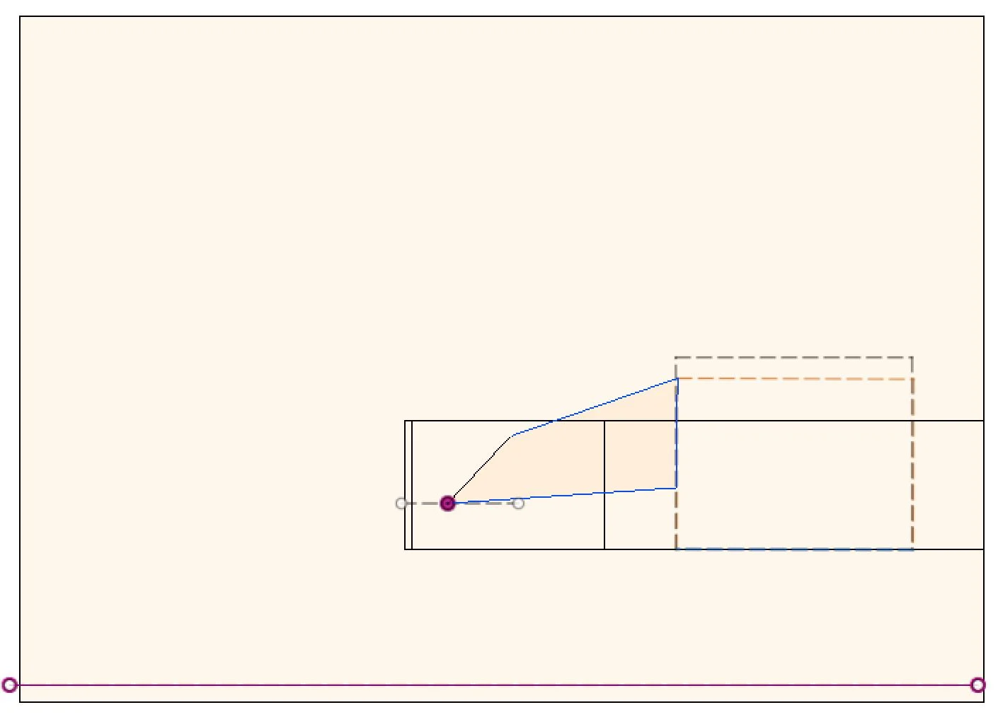
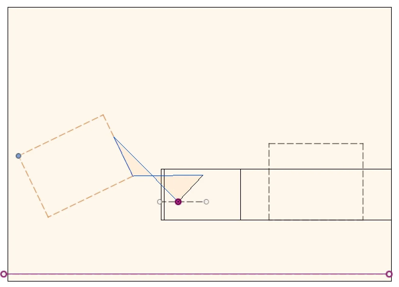
A flat bed truck was considered as shown in Figure 1 and 2. The task was to design a suitable mechanism that will lift a rectangular container from the ground and move it to the back of the truck. The important dimensions that had to be taken into consideration are shown as well in the figures below (i.e. container dimensions, AB = 0.91m, AC = 1.12m, AE = 1.37m). In addition, the design should be a planar linkage with mobility m = 1.
For the design of the mechanism, the box must not exceed the workspace beyond the dotted lines of the large bounding box and fall within the dotted lines denoted by ABCD on the bed of the truck. The shaded region on the bed of the truck must also contain the fixed pivot. With the depth of the usable area shown in Figure 2.
Prior to applying the three-position graphical synthesis, certain key assumptions and considerations were made in addition to the requirements. These included the assumptions that:
1. The final position of the box, as indicated by the dashed lines, is in the center of the empty area of the flat bed truck.
2. The lid of the box denoted by ABEF would always be secured as the box is lifted onto the truck with a lock at the front.
3. Contents of the box are not fragile and have to be kept in an upright position.
4. The wheels of the box are not specified and can either be removed or vary with the required start position of the box.
5. The rear door of the flat-bed truck would be down and not interfering with any movements of the linkages.
6. The walls of the truck where the ground pivots would lay will not buckle due to the stresses of the linkages or the weight of the load.
7. The mechanism would be held in the final position as the vehicle drives off.
In addition, using the examples form Theory of Machines and Mechanism, Fifth Ed., it can be observed that on the pages 34 – 35, that we need a drag-link linkage that would allow the both the crank and rocker to move the full length of motion as shown in (c) [1], allowing flexibility for the positioning of the box. This has to satisfy Grashof’s Law.
At the beginning of the project, certain assumptions were made, including the lid of the box remaining close throughout the movement of the box. However, to ensure that the box is not only supported by the coupler link, the box would be secured to at the base the wheels would act as locks to hold the box in place. This design would also allow a strap to be attached around the box as it is moved, securing the lid of the box further. This design can be seen in drawing and CAD below.


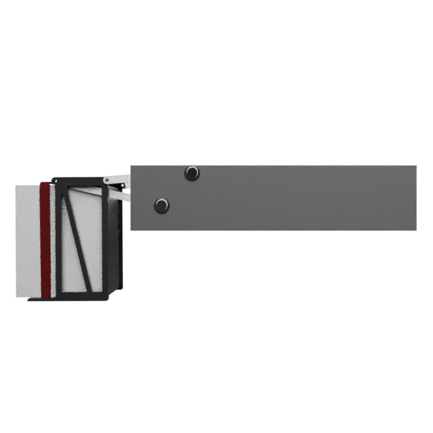


Taking into consideration of the weight of the box, it is possible for the construction of this mechanism to be make of square extrusions and it to be actuated with a single linear actuator on both sides of the vehicle. This would be a rather cheap and sturdy construction. Alternatively, if the weight of the box is heavier, it is possible to consider a truss like construction for the linkages with similar actuation of the input link.
For the mechanism to turn smoothly, an A-frame will be attached to the base of the truck, supporting the rotating input pivot. This will safely secure the rotating shaft of the input link and be secured to the bed of the truck. When the box has been moved onto the truck bed, the mechanism would remain in that position to hold the box securely in place, to ensure that the box does not move during transit. Furthermore, locks on the linkages will prevent any unnecessary movement of the linkages during that time, ensuring that the box is secure to the bed of the truck. To ensure minimal stresses on the linkages if the box were to shift, straps could be attached to the box with a ratchet strap across the box to the truck.
The cost of manufacturing will be relatively cheap. Considering the materials mentioned above, including motor, servo or actuator, the cost is relatively inexpensive. In addition to that, a large scale production can decrease the overall production cost of the mechanism. Since no modifications are necessary to the box, it is predicted that the mechanism can fit numerous sizes of boxes as the strap securing the box and the mechanism can be adjust to the box size, increasing the versatility and, thus, the marketability.
Given the right equipment in an engineering solutions company, it is also possible for the entire mechanism to manufactured in-house. The predicted man-hours are about 1 week for structural analysis and design and about 2 weeks for the manufacturing including cutting, welding and assembly. Totally roughly 3 weeks of manufacturing and costs for materials that include actuation, steel square tubing, fasteners and bolts and mild steel for the securing A-frame.
For the model, the pieces were first CAD out and scaled to 1:10. This allowed a reasonable thickness of the links to be built, ensuring sturdy construction for the model. The pieced were them secured to a plywood board for stability and the rest of the model draw to 1:10 scale to emphasize the workspace of the container movement. The final construction can be seen in below. The pieces of the links and the truck bed were 3D printed with the depth of the links only taking up two thirds of the allowed grounding space for the ground links.


The links are shown by the blue length and the position of the bottom surface of the box at its initial position is shown by the red line at the bottom edge of each CAD sketch. The difference between the red line and the bounding box is the distance the wheels on the box will have.